A HISTORY OF FLAT GLASS CUTTING EQUIPMENT
Written by: Bob Lang, Retired Solution Specialist from Billco Manufacturing in 2018
As one recalls the progression of flat glass cutting from the early 1900s to today, there have not been very many major iterations of equipment designs to get where we are today.
As glass producers changed from producing glass in large round cylinders to flat drawn vertical or horizontal processes in the early 1900s, scoring the glass surface with a small wheel or another hard item, held by a wooden hand tool was the order of the day.
Large lites of glass were cut (or “capped”) from the continuous ribbon of glass, placed on bucks (racks), and delivered to hand-cutting areas of the factory. The hand-cutting area looked like rows of horse stalls. In each stall was a man with a wooden hand-cutting tool (usually diamond tipped), and a large table. The environment was dark and dirty.
As the racks of large glass lites were delivered to the stalls, the men scored and separated the lites into smaller squares or rectangles. The sizes they cut correspond to the stock glass sizes that the glass producer sold to the local glass shops around the country. These stock lites were interleaved with sawdust or paper and were shipped in wooden boxes.
An interesting side note is that Billco, at that time under the family name of Klages, had its beginnings in the early 1900s making these diamond-tipped hand-cutting tools as one of its products for the glass industry.
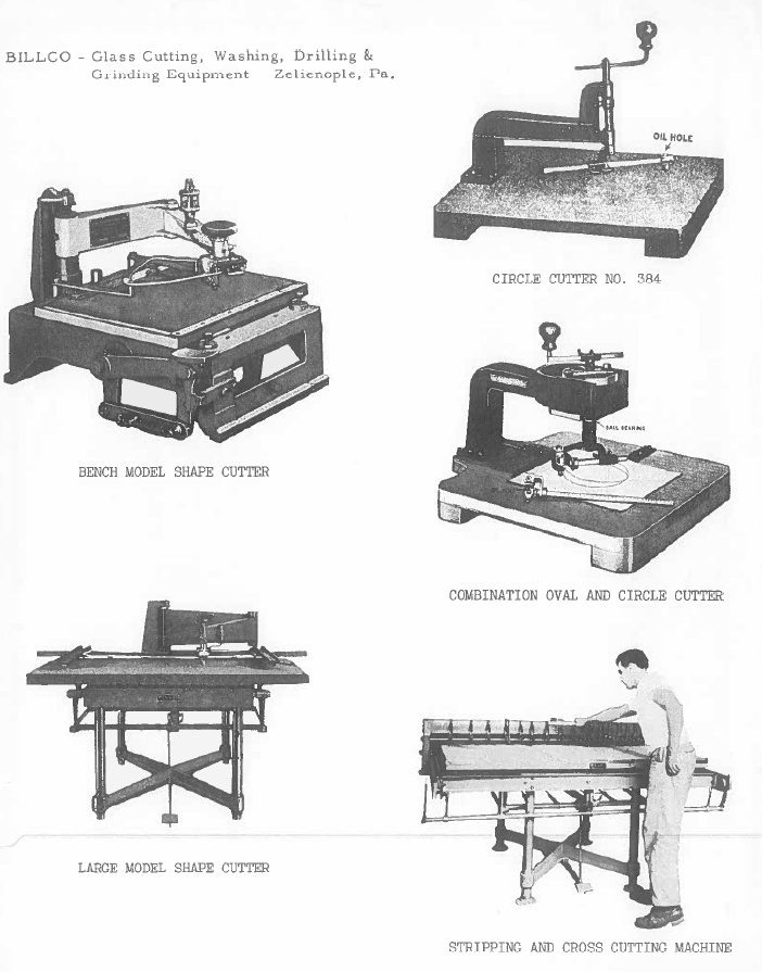
The First Commercially Produced Cutting Machines
Machines for cutting shapes were developed in the late 1920s / early ’30s, almost 30 years before straight-line cutting machines were produced.
The first shape-cutting machines were designed for cutting circles and ovals were manually operated. Klages began selling these circle and oval machines in the 1930s to distributors selling supplies to the glass industry, as well as directly to companies who were producing clocks, mirrors, gauges, optical devices, and other items that required a glass cover plate. These machines could produce parts from 1” to 36” in diameter.
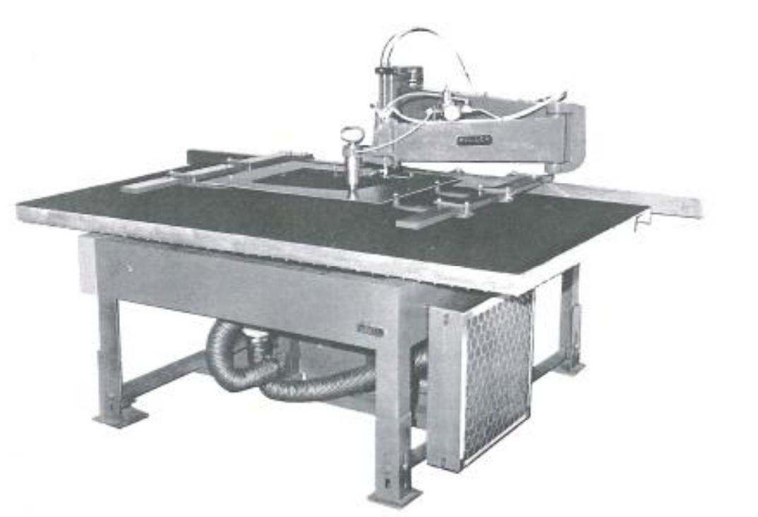
Manual Shape Cutter with Model 55 or 67 Cutting Head
As automobiles began using glass in the 1930s, and the automobile designers demanded windows in shapes other than rectangles, manually operated shape-cutting machines were developed. These machines utilized a two-part arm assembly supporting a pneumatically operated head that held a cutting wheel. This assembly looked exactly like a person’s upper and lower arm, and hand. The assembly pivoted at the upper arm from a heavy post attached to the back of the cutting table. A template was made from wood or metal in the shape of the desired part. This template was suspended over the cutting table, just above the stock lite of glass lying on the table.
The cutting head was designed to follow this template as the operator moved the arm and head assembly around the template. The pneumatic head forced the cutting wheel down to the glass, which placed a score on the glass in the shape of the template as the operator moved the arm/head assembly around the template. After scoring, the glass was moved to an adjacent table for score separation. These shape-cutting machines were not only used in the automotive industry but in the mirror industry as well. Manually operated shape-cutting machines ranged in size from 20”x 20” to 44”x 94”. An example of one of these machines is shown below.
Even some large glass wholesale shops had at least one shape-cutting machine, as well as one or two oval/circle cutters. In order to reduce operator fatigue in high-production automotive shape cutting lines, a motor and belt assembly was introduced in the 1950s, to power the cutting head around the template. These manual and powered shape-cutting machines were prevalent until the late 1970s when a revolutionary new concept was introduced to the industry, as you will see later in this discussion. However, some of these shape-cutting machines are still being used in factories in some parts of the world.
Straight-line Cutting Machine Technology Developed Slowly
Straight-line cutting can be defined as cutting of squares, rectangles, or trimming edges from the stock size glass sold by glass manufacturers. Surprisingly, it took until the late 1940s before any type of automated equipment for straight-line cutting became commercially available. Until then, straight-line cutting was done on tilting or stationary tables, with hand-cutting tools and straight edges. There was one exception to this… the automation of the cutting (“capping”) of stock sheets from the continuous vertical and horizontal glass ribbons, after the glass was cool enough to be handled. Billco built this type of equipment for glass producers, and I assume other companies did as well.
Sometime in the late 40s, our company started offering what was called Pin‐bar Tables, which were designed to lessen hand-cutting fatigue and produce more accurate cut parts. These Pin‐bar Tables consisted of a large table with a row of pins along the sides of the table surface. These pin‐bars were actually ¼” thick, 2” wide steel strips embedded into the edges of the table, below the surface. The strips had ¼” holes drilled on 1” centers in the middle of the strip. Steel pins were inserted into the holes and only projected up to the surface of the table so that glass could be loaded onto the table without hitting the pins. Using the pins as measurement points, a special cutting bar that spanned the width of the table was inserted into the corresponding pins on both sides of the table. Using this accurately positioned bar, a person could run his hand tool along the bar to accurately score the glass.
This eliminated measuring for each cut and then used a “T” square for alignment of the hand-cutting tool. There were some versions of this table where a cutting head and rail were attached to the bar, and the operator pulled the cutting head across the bridge. The Pin‐Bar Table did not automate straight‐line cutting, but it did speed up the hand-cutting process and make the finished parts more accurate.
In the late 1950s, commercially available, powered straight‐line cutting machines called Strip Cutters were developed. It is important to note that all scores produced on a strip-cutting machine went completely across the glass lite from one side to the other. These strip‐cutting machines were available in three basic designs known as Powered Stip Cutters, Traversing Single-Bridge Strip Cutters, and Dual-Bridge Cutters.
Powered Strip Cutters:
This machine consisted of a fixed bridge with multiple, adjustable, pneumatic cutting heads mounted on it. A powered roller was mounted under the bridge for driving the glass lites under the cutting bridge (and heads). Positioned before and after the bridge was a bed (or table) of rollers for loading/offloading, and supporting the glass as it passed under the bridge. The result of this design was that at the offload end of the roller table, the glass lite was scored into multiple strips… or if only one head was used, the lite had been scored on one side, reducing the lite in width.
These machines were available in 36” to 96” widths, and were used primarily by window manufacturers who stocked many different sizes from the glass producers. These stock sizes were close to the finished window sizes they offered. They would select a stock size close to the window they wanted to produce, then use a powered stripper to trim one or two edges to the desired finished size.
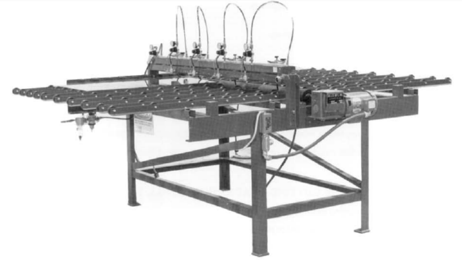
Manual Shape Cutter with Model 55 or 67 Cutting Head
Traversing, single‐bridge strip cutting machines:
These machines were available in size ranges from 25” x 52”, to 48” x 94”. They consisted of a fixed, air float table to support a lite of glass, with a powered cutting bridge traversing the narrow dimension of the table. Multiple, adjustable cutting heads were mounted on the bridge.
This machine had a very unique method of cutting stock lites of glass into smaller squares or rectangles. If you started with a 24” x 24” stock lite and wanted to cut it into 2”x 4” squares, you set the heads on the left half of the bridge on 2” centers. The heads on the right half were set on 4” centers.
The operator loaded the stock lite on the left first and pressed a button, causing the bridge to proceed forward and return, scoring the lite on 2” centers. Next, the operator rotated the glass 90°, placed it against squaring stops on the right side of the table, and again pressed the button. After the bridge had traversed forward and back the second time, the lite was now scored in both the 2” and 4“ dimensions and ready for score separation on an adjacent table.
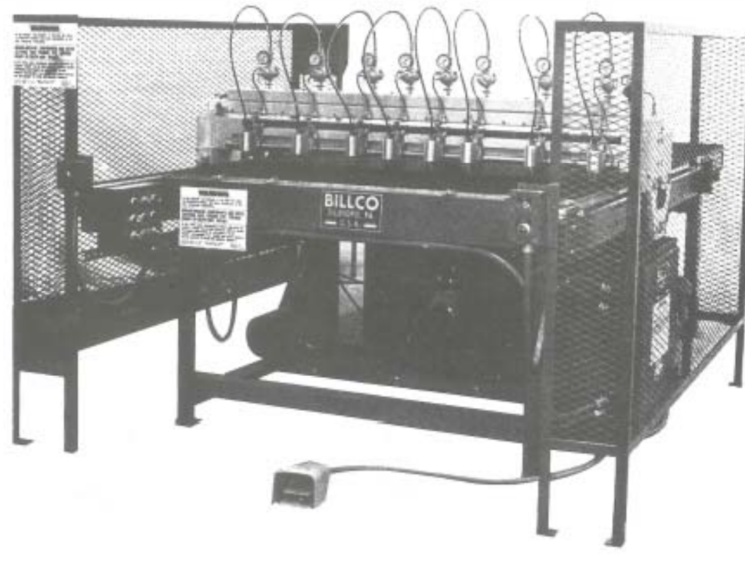
Manual Shape Cutter with Model 55 or 67 Cutting Head
Many of these single‐bridge machines were used by companies that were producing shaped or circular glass parts. On the strip cutter, they would cut large stock sizes down to size very close to the finished shape part they wanted to produce. Then using a shape-cutting machine, they would cut the shape part from the small blanks. This method kept the glass waste to an absolute minimum.
Dual‐bridge cutting machines (also referred to as Block Cutters or X‐Y Cutting Machines):
This machine has a fixed, air float cutting table in general sizes from 48” x 48” to 96”x96”. In two automated cycles, two bridges (one able to pass over the other), with multiple, adjustable cutting heads on each bridge, traversed across the table in each dimension. After the second cycle, the glass has been scored in both the X and Y-axis dimensions. Our company also produced automatic breakout (score separation) machines to accompany this cutting machine. X‐Y Cutting Machines were primarily used by the glass producers, to reduce the large lites cut from the glass ribbons down to stock sizes supplied to their customers.
These three strip-cutting machines were very popular in the glass industry, and actually, some of them are still being used in glass fabricating facilities around the world. There were also some other semi-automated versions of straight‐line cutting machines being used in various glass plants throughout the world… mostly by the companies themselves, to meet their unique needs.
It is also once more important to point out that none of these strip-cutting machines could score a stock lite of glass into a group of random size rectangles or squares.
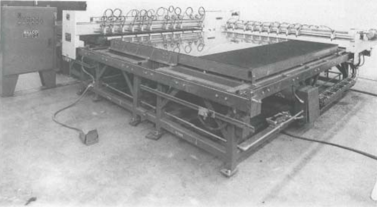
Dual‐bridge Cutting Machines
Glass Passed Through Several Steps From Producer to End User:
In general, the progression of glass from the glass manufacturers to the finished glass used by the consumer went through one or two different steps before it reached the end user. For residential and commercial building glass, the glass was shipped in wooden cases, in large stock sizes, from the glass manufacturer to a glass distributor located in a large metropolitan area. The distributor cut these large stock sizes down to smaller sizes that the local glass shops could handle. In almost all cases, the glass distributors and shops relied exclusively on tilting or stationary hand-cutting tables for glass cutting.
Vertical, hand-cutting machines were and still are used in glass shops and hardware stores to trim larger lites of glass down to smaller finished sizes for the end user.
For windows, as well as auto glass and mirror producers, the glass manufacturer supplied directly large quantities of stock sizes in boxes or on racks that were close to the actual finished parts they produced. These companies then used their powered strip cutters, and/or shape-cutting machines, to reduce the stock size to the desired finished rectangular or shape parts.
No matter what the end use of the glass part was, in many cases, it had to be processed on more than one type of glass cutting machine.
The Dawn of a New Generation of Glass Cutting Technology and How Glass Was Sold To Consumers:
A meeting at Billco in 1970 started a change in the way glass cutting machines would be designed and controlled. This new technology is still in use on glass cutting machines today.
The purpose of the meeting was to determine if there might be faster and more accurate control methods, as well as machine design, for cutting shaped glass parts for the automotive industry. The meeting was attended by the principals of Billco, the chief engineer, and myself.
Fortunately for our company and ultimately the glass industry, our chief engineer, Hugh Trautmann, was a brilliant mechanical engineer who had extensive machine tool experience, as well as experience in designing and producing aircraft parts for such companies as McDonnell Douglas and Boeing. He also was a person
who didn’t mind acting on hunches he thought might work. He was the right person, at the right time in glass industry history.
Hugh was up for the task. After evaluating Tracer‐type Control and Numerical Control (NC), both of which were in use at the time in the machine tool industry, he settled on NC technology. NC was being used for controlling milling machines in the metalworking industry. There were some obstacles to be overcome with Numerical Control, as it was being used at that time. The greatest problem by far was the machine speed of a standard milling machine…around 100 to 200 inches per minute….much too slow for shape glass cutting. Hugh’s goal was to start out at cutting speeds of possibly 1000 inches per minute. Selecting a standard Mark Century™ NC Control from General Electric, and after much study, he found unique ways to get around this speed problem and make NC useable on a glass cutting machine.
The next step was to design a cutting machine to accept this new control technology. Here Hugh relied on his experience in the aircraft industry by using ball screws to support and move a traversing bridge. These ball screws were similar to those used on aircraft to raise and lower wing flaps and landing gear. The bridge supported a single pneumatic cutting head, holding a standard tungsten carbide cutting wheel. The framework of the machine was built from massive square steel tubing to support both the cutting table and the cutting bridge and ball screw assembly suspended above the cutting table. The reason for the ruggedness of the machine frame was to eliminate the vibration of the machine at the high cutting speeds, which could affect both cutting accuracy and the smoothness of the score path.
The next step was to design a cutting machine to accept this new control technology. Here Hugh relied on his experience in the aircraft industry by using ball screws to support and move a traversing bridge. These ball screws were similar to those used on aircraft to raise and lower wing flaps and landing gear. The bridge supported a single pneumatic cutting head, holding a standard tungsten carbide cutting wheel. The framework of the machine was built from massive square steel tubing to support both the cutting table and the cutting bridge and ball screw assembly suspended above the cutting table.
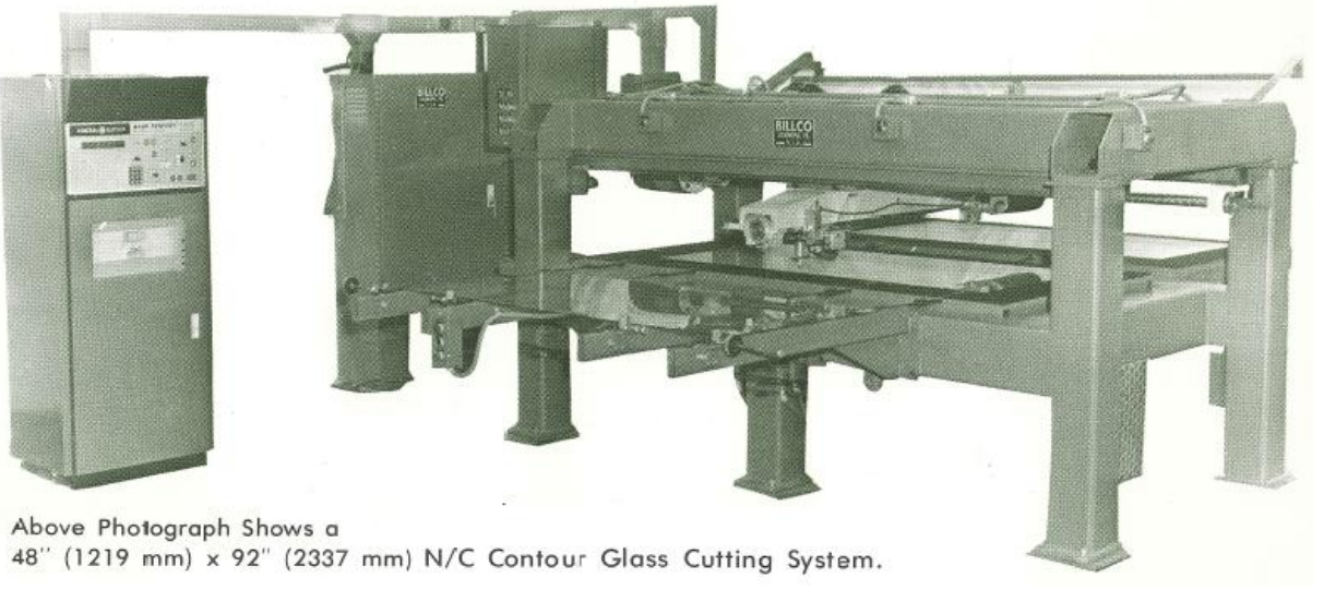
The reason for the ruggedness of the machine frame was to eliminate the vibration of the machine at the high cutting speeds, which could affect both cutting accuracy and the smoothness of the score path. After testing and overcoming detractors both in our company and in the glass industry, this prototype machine was sold to PPG at their Greensburg, Pa. auto glass plant…and remained in operation at that plant until it closed in the late 90s / early 2000s.
These NC / X‐Y Axis, Contour Cutting Machines, were sold both in the US and Europe, and served the automotive industry well for many years.
Taking a Bold Second Step in Straight‐line Cutting:
Also in the early 1970s, some decisions were being made in other parts of the glass industry that helped to revolutionize straight‐line cutting machine technology and combine it with NC shape cutting. This new technology is still the norm in glass cutting machine design today.
These decisions included:
Glass Packaging:
Float glass manufacturers decided to make available to glass fabricators large stock glass sizes up to 130” x 204”. The reason this was unique, was that they packaged this glass, not in wooden cases, but rather in 10,000 lb. packs, referred to by one company as StoceTM packs. The packs could be delivered to glass fabricators by truck, on specially designed low‐slung trailers. Using an overhead crane, these packs were moved from the trucks to storage racks using nylon slings.
Tempering:
The glass machine company Glasstech Inc., located in Perrysburg, Ohio, and the leading manufacturer of flat glass tempering furnaces, revolutionized the residential and commercial tempered glass industry, by designing a large-width, batch‐type tempering furnace. Instead of being a very long, high-speed, continuous furnace, this shorter 84” wide furnace was designed to accept a batch of large or small glass parts in random sizes of the same thickness. The batch was processed through the heating chamber on ceramic rollers, and then into a unique quench (cooling) area. In both areas, the batch would oscillate back and forth on the rollers as it progressed through the furnace. Hence, this new furnace came to be known as an oscillating, batch‐type tempering furnace.
A New Way to Offer Tempered Glass to End Users:
Using the above new packaging and tempering technologies, a revolutionary new type of glass industry business was born by the name of Tempglass Inc. The purpose of this business was to supply random (custom) sizes, thicknesses, and quantities of tempered glass to anyone who needed them. The principals of this custom tempering business were the company Indal‐RTZ, a worldwide leader in the construction materials industry, and two of the owners, Norman Nitschke and Harold McMaster of Glasstech Inc. This new venture completely changed the concept of how tempered glass was marketed
and ultimately used in the world. Tempglass Inc. was cloned several times around North America. It also became the template for many other custom tempering operations by other glass fabrication companies.
A New Cutting Machine Design:
Tempglass Inc. asked Billco to build a cutting machine and loading system that could produce random (custom) size glass parts from the very large stock glass sizes they were going to buy from the float glass producers. As I have mentioned previously, up to this point all cutting machines could only produce scores in checkerboard layouts, and thus large quantities of the same sizes. Billco accepted the challenge, and once again called on Hugh Trautmann to design a machine. Using the Numerical Control based technology that he had recently developed for shape cutting, Hugh designed a totally different-looking machine. This machine had a fixed cutting table with conveyor belts and a cutting bridge that spanned the narrow width of the cutting table but was mounted on rails at the side of the table instead of being suspended above the table. The cutting bridge supported a single traversing cutting head.
The exciting thing about this new cutting machine design was that it not only could score the large stock sheet into random size rectangular or square pieces (block sizes), it could also score shapes inside the blocks. The cutting tables started out in 130” x 170” sizes but quickly were upgraded to 130” x 204” in size. This new cutting machine technology became known as NC‐XYZ / Contour glass cutting.
To load the large stock glass onto the cutting machine table, an automatic loading machine was developed. This machine could pick up and tilt single large stock lites from the vertical racks to a horizontal roller conveyor, and then convey them onto the cutting machine conveyor belts. An air float breakout table completed this unique glass cutting system. In 1976, Billco delivered to the Tempglass Inc. location in Perrysburg, Ohio, this revolutionary new glass cutting system, the concept of which is still being used all over the world today.
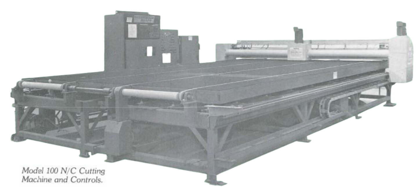
Needless to say, the 1970s were some very exciting years in the growth of the flat glass cutting machine industry. The above events totally changed the way straight‐line glass cutting was accomplished in the glass industry throughout the world. These machine design concepts are still being used today by many glass equipment builders throughout the world. There have been many upgrades over the years, but the basic, traversing bridge with a single cutting head concept still remains the foundation of all XYZ/Contour machines.
Although the original machine had cutting speeds of 1000 inches per minute, with new magnetic‐linear motor technology current machines are cutting at 7000 to 9000 inches per minute. The original Numerical Control technology became Computer Numerical Control (CNC) and has much more control capability than the original versions first used in 1976. Automatic loading systems from multiple glass racks have been developed and installed to improve the glass loading process. In some cases, automatic score separation machines have been developed to use in place of hand separation on breakout tables.
Due to the advent of metalized coatings being placed on glass starting in the late 90s and early 2000s, glass cutting machines have been required to remove (“delete”) strips of these coatings around the perimeter of some pieces of coated glass during the glass scoring process.
This has been accomplished by mounting a second CNC‐ controlled head on the cutting bridge. This “edge, or coating deletion” head carries a special grinding wheel that removes these thin coatings, while not damaging the glass.
Previously, this “deletion” process was done on stand‐alone machines after the cutting process.
The cutting machine shown above is typical of the high-speed, CNC / XYZ‐Contour glass cutting machines, equipped with both scoring and deletion heads that are in use today.
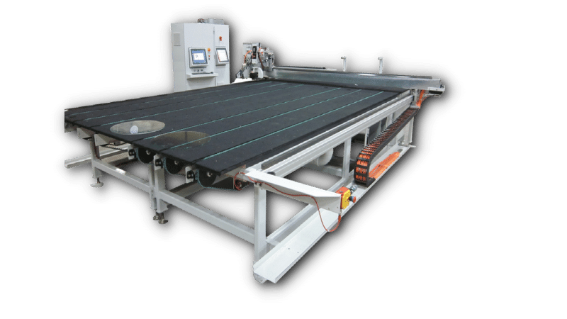
CNC 2200
Challenges and Solutions of the New Technology:
One of the greatest challenges to operating an NC, and then CNC contour glass cutting machine, was how to program the machine control. This was a two-part problem. First, was how to produce the step‐by‐step control program to cause the machine to move the cutting bridge and head assembly, in such a way that the desired shape was scored on a glass lite that was laying on the cutting table. The method to program the NC control used originally in 1971 for shape cutting was to first digitize the shape part so that it was described in X and Y coordinates. Then, using the coordinates, manually generate a series of movements using a control language specifically developed for Numerical Control. After the program was generated, it was typed into a Teletype machine that produced the program on a punched paper tape. This tape was loaded into the control’s reader and caused the Numerical Control to send electrical commands to the motors on the cutting machine bridge and head to accomplish the desired cutting path. Although laborious, this worked successfully since the number of unique shapes in the automotive industry was relatively small.
A computer software program, using the coordinates, the NC language, and the specific commands unique to the cutting machine, was developed to eliminate manual programming. The paper tape procedure was used for only a few years until computers were merged into Numerical Controls. Within the onboard computer, a CNC software program could produce a cutting program and convert it into machine language, all within a matter of seconds.
The second problem was unique to the XYZ / Contour cutting machine introduced in 1976. Instead of producing a simple layout of X and Y checkerboard score lines on a lite of glass, as automated cutting machines had to do up to this point in time, this machine had to produce X and Y straight‐line scores in a random layout of block sizes, and place shape scores within some of the blocks.
This was a three‐fold programming problem:
Any shapes to be cut had to be digitized and described in X and Y coordinates, then stored in a computer file. All the various block sizes to be produced for a certain time period had to be defined by size, glass thickness, and type of glass and then stored in another program. After sorting the sizes by glass type and thickness, each category of sizes then had to be “optimized” (the process of fitting the blocks onto the large stock sizes in order to get the least glass waste on each stock lite). Borrowing some technology being used at the time in the plywood industry, a rudimentary software program for optimizing was
developed to meet the needs of the first generation of cutting machines. However it took a decade or more, and many software engineers from various companies to develop the very sophisticated Glass optimization software that is being used today.
After generating an optimized layout of random block sizes for each stock lite of glass, a unique NC cutting path program for each lite of glass had to be generated, including placing any shapes to be scored within the blocks. This problem was daunting. Some X and Y score lines went completely across the lite of glass, and others started and stopped between intersecting perpendicular lines. Some scores crossed over each other, while other scores stopped short of intersecting with another perpendicular score. All these individual programs had to be combined and converted into a Numerical Control program to operate the XYZ / Contour cutting machine.
One interesting result of all the above work was the XYZ nomenclature for the cutting machine. While X and Y described all the various straight‐line scores on a layout, an X or Y score line that intersected, but did not cross over a perpendicular score, became known as a Z score. Although using XYZ became an easy way to identify the type of cutting machine and its capabilities, the score identified as Z has always caused some controversy… because a Z movement in Numerical Control language is actually a vertical movement. Cutting machine manufacturers have worked around this issue in various ways by using
different descriptions for their machines and their operation, but in the end when someone talks about an XYZ/Contour glass cutting machine most people in the glass industry know what capabilities the machine has.
Just to complicate this nomenclature issue further… when XYZ/Contour cutting machines first began to be used in the window industry (as you will read in the next section), some newer machine manufacturers referred to the actual cutting machine simply as an “Optimizer”. The words “glass cutting machine” were not used. This really caused some confusion in the already established glass cutting industry, but now most people in the industry have accepted or at least understand that the machine referred to as an “Optimizer” is actually an XYZ/Contour cutting machine.
CNC Cutting is introduced into the Window and Door Industry:
There was another significant development in the 1980s, that made XYZ/Contour machine cutting available to window manufacturers and other glass fabricators. This group of glass users did not have the means to handle the very large sizes and packs of glass being supplied to the temperers and other large glass fabricators.
For the thicknesses used by the window industry, the glass manufacturers began offering shrink-wrapped packs of 72” x 84” glass, weighing in the 3,000 to 5,000 lb. range, and shipped on returnable steel glass racks. These racks could easily be handled in low-ceiling buildings, by fork trucks instead of overhead cranes. In order to load this glass from the racks to the cutting machines, a technique called “free‐fall” was used. This technique had been used in the Australian glass industry for many years.
The “free‐fall” technique involved placing the racks on stands so that the bottom edge of the glass was at the same level as the cutting machine table. The racks were located immediately beside the cutting table, or a separate air float loading table, an operator caused single lites of glass to fall from the racks onto the table. The lite was supported by a cushion of air as it fell onto the table surface. The lite was then floated onto and into position on the cutting table for scoring. To complete this process, the cutting machine manufacturers developed smaller versions of the XYZ/Contour cutting machines to process this smaller stock-size glass. This cutting system became very popular, and many machines were sold by multiple machine manufacturers over the years.
The picture shows an automated free‐fall system connected to a cutting machine. The free‐fall device can traverse between multiple glass racks placed along each side of the table.
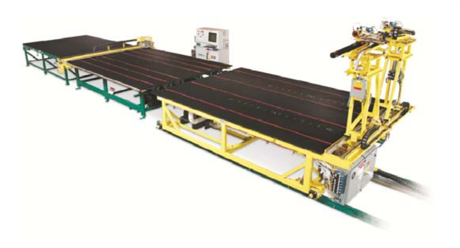
Auto Free Fall System
What Lies Ahead?
As of this writing in 2018, glass cutting technology utilizes the methods and machine concepts developed in the 1970s. It is very efficient, both in minimizing glass waste and producing the glass pieces used throughout the Glass and Fenestration industries. Some companies have developed glass scoring alternatives such as performing the score with lasers. Although successful, these methods are thus far very slow and not practical for today’s high production glass cutting requirements.
It will be very hard to find something that is as fast as today’s cutting machines. The cutting wheels provide many miles of scoring and can be re‐sharpened several times. But just like the computer industry, you never know what new technology is just around the corner. Find out what has been updated to our equipment by talking with a Solution Specialist.
